domingo, 10 de agosto de 2014

power line plc integrado

power line plc integrado

http://www.arianecontrols.com/powerline.php


http://www.microchip.com/Developmenttools/ProductDetails.aspx?PartNO=AC164145


http://www.hth.com/plm-24/plm-24.htm


TI lowers barrier for power line communications with new kit and software library plcSUITE

http://www.electronicspecifier.com/around-the-industry/ti-tmdsplckit-v2-plc-development-kit


TI lowers barrier for power line communications with new kit and software library plcSUITE

martes, 29 de julio de 2014

jueves, 23 de enero de 2014

chipKIT Lesson: SD Card

chipKIT Lesson: SD Card

January 2nd, 2013  Posted at   ChipKIT Lesson
arrow   |   No Commentsarrow
SD Card Module top
SD Card Module bottom
Sekiranya projek memerlukan simpanan data yang besar, tidak mencukupi dengan simpanan di dalam microcontroller ataupun simpanan di dalam external EEPROM, SD Card boleh digunakan. SD Card boleh interface melalui SPI dan menggunakan FAT (File Allocation Table) system.
SD Card disambungkan menggunakan empat pin iaitu MISO, MOSI, SCK dan SS. Pin-pin pada chipKIT Max32 adalah
  • MISO = 50
  • MOSI = 51
  • SCK = 52
  • SS = 53
Berikut adalah videonya
ChipKIT Source Code
1 2 3 4 5 6 7 8 9 10 11 12 13 14 15 16 17 18 19 20 21 22 23 24 25 26 27 28 29 30 31 32 33 34 35 36 37 38 39 40 41 42 43 44 45 46 47 48 49 50 51 52 53 54 55 56 57 58 59 60 61 62 63 64 65 66 67 68 69 70
#include <SD.h>
 
#define chipSelect 53
File myFile;
 
void setup()
{
Serial.begin(9600);
pinMode(chipSelect,OUTPUT);
if (!SD.begin(chipSelect)) Serial.println("initialization failed!"); //Initializes the SD library and card.
else Serial.println("initialization done.");
}
 
void loop()
{
int data;
Serial.print("1:Check file exist ");
Serial.print("2:Create file ");
Serial.print("3:Remove file ");
Serial.print("4:Write file ");
Serial.println("5:Read file");
while(!Serial.available()) continue;
data=Serial.read();
if (data=='1')
{
if (SD.exists("example.txt")) Serial.println("example.txt exists."); //Tests whether a file or directory exists on the SD card.
else Serial.println("example.txt doesn't exist.");
}
if (data=='2')
{
Serial.println("creating example.txt");
myFile = SD.open("example.txt",FILE_WRITE); //Opens a file on the SD card.
myFile.close(); //Close the file
}
if (data=='3')
{
Serial.println("removing example.txt");
SD.remove("example.txt"); // delete file:
}
if (data=='4')
{
myFile = SD.open("example.txt",FILE_WRITE); //Opens a file on the SD card.
if (myFile)
{
Serial.println("writing to example.txt");
myFile.println("shahrulnizam.com");
myFile.close(); //Close the file
}
else Serial.println("error opening example.txt");
}
if (data=='5')
{
myFile = SD.open("example.txt"); //Opens a file on the SD card.
if (myFile)
{
Serial.println("reading from example.txt:");
while (myFile.available()) Serial.write(myFile.read());
myFile.close(); //Close the file
}
else Serial.println("error opening example.txt");
}
Serial.println();
}
view raw chipKIT SD Card hosted with ❤ by GitHub
Nuffnang Ads

Dah baca, tinggalkan komen anda disini


Raspberry Pi + PIC18F4550 TC74 USB

Raspberry Pi + PIC18F4550 TC74 USB 


http://www.janwagemakers.be/wordpress/?p=182

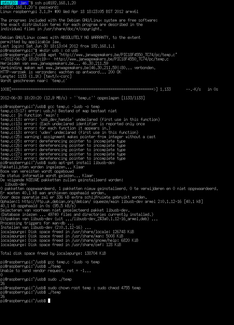
So, now that I have a Raspberry Pi and I can read the temperature with a TC74 over USB, I thought it would be nice to combine them together.
Because the Raspberry Pi makes use of the ARM architecture, a re-compilation of temp.c is necessary.
(click for larger image)
After compiling temp.c, everything just works™ like on a normal PC… Great! :)
As a test, I have then installed a webserver (boa) on the Raspberry Pi and created a little webpage that displays the current temperature.
The index.html of this simple webpage looks like this:
<html>
<head>
<meta http-equiv="Refresh" content="4">
</head>
<body style="margin:0px;" background="background.png" text="#000000"  bgcolor="#E0E0E0" link="#0000FF" vlink="#800080" alink="#FF0000">

<center>
<h1>Test : Raspberry Pi Debian GNU/Linux + PIC18F4550 TC74 USB</h1>
</center>
<hr>

<center>
<h2>The temperature is now <b><script type="text/javascript" src="/cgi-bin/temp"></script><noscript>No JavaScript support!</noscript></b>C.</h2>
</center>

</body>
</html>
And cgi-bin/temp looks like this:
#!/bin/bash
echo Content-type: text/html
echo
echo "document.write(\"`/home/pi/usb/temp`\");"
When I connect with a normal web browser to the Raspberry Pi, I get a simple webpage that displays the temperature:
It should also be possible to connect a TC74 directly (via I²C) to the GPIO pins of the Raspberry Pi, mmmm,… maybe something for a next post

Ways of Linking Raspberry Pi with Arduino Using GPIO, Serial, USB, I2C

Ways of Linking Raspberry Pi with Arduino Using GPIO, Serial, USB, I2C


There are only limited number of GPIO pins available on the Raspberry Pi, so it would be great to expand the input and output pins by linking Raspberry Pi with Arduino.
There are so many ways of connecting the Raspberry with Arduino. Recently [Oscar Liang] posted some tutorials on how to connect the two devices using different methods, including using USB cables, using GPIO pins on the Raspberry Pi and serial pins on the Arduino and using I2C communication.
arduino_plus_raspberry_pi_cropped-600x293

Linking Raspberry Pi with Arduino Using USB Cable

This is a very straight forward method, he basically setup serial communication on both devices, so they can be listened or write to each other. The Advantage about this is simplicity, all you need is a USB cable. The down side is, it takes up a valuable USB port, that you can use somewhere else.
raspberry-pi-to-arduino-via-usb-cable
Detail can be found here: http://blog.oscarliang.net/connect-raspberry-pi-and-arduino-usb-cable/

Linking Raspberry Pi with Arduino Using Serial Pins and GPIO Pins

Another Method is using the serial pins on the Arduino to connect to the GPIO pins on the Raspberry Pi.
This is in some way similar to the above connection, but this time we are not using the USB port. The bad news is, you might need extra hardware to run this safely –  a logic level converter because of the running voltage level difference between the two device.
There have been some arguments about whether a converter is needed on the internet. As some people suggest a voltage divider would do the job.  I won’t go through the technical detail here, but I strongly recommend using a logic level converter.
arduino-raspberry-pi-serial-gpio-connect-schematics
Detail can be found here: http://blog.oscarliang.net/raspberry-pi-and-arduino-connected-serial-gpio/

Linking Raspberry Pi with Arduino Using i2c Communication

This way is so far the best way we have seen on the internet – using I2C. It does not need any additional hardware (a couple of cables does not count), it does not use your USB port, and it’s very easy to setup as well.
Again there are concerns about the voltage level difference between the two devices (the Pi is on 3.3V and Arduino on 5V), if there were connected together the Pi might be damaged. However, it does not seem to be the case for I2C. It turns out there are pull-up resistors that protects the Pi.
Raspberry-PI-I2c-Arduino-connected
Detail can be found here: http://blog.oscarliang.net/raspberry-pi-arduino-connected-i2c/

Controlling LED brightness using PWM pic

Controlling LED brightness using PWM

A Guide to LED brightness control

Pulse Width Modulation or PWM is a term you hear a lot if you are interested in controlling power output using a microcontroller. It has many applications, although one of the most popular amongst hobbyists is controlling the brightness of LEDs. In this tutorial we will cover the basic principles behind PWM and how it can be used for LED brightness control including fading out LEDs rather than just turning them on and off.
This article will focus on some of the more specific details of the PIC18F range of microcontrollers; however the techniques and principles are the same for all other microcontroller products. Some microcontrollers include PWM modules which perform all of the hard work for you; however this article focuses on the more universal (and scalable) technique of using interrupts.


Contents

[hide]

Video Tutorial

This tutorial is primarily designed as a video tutorial. You can watch the full video on YouTube, please use 780p or 1080p for clearer diagrams:


Introduction

To control the brightness of an LED you can vary the power which is sent to the LED, for example using a potentiometer (variable resistor), the more power the LED receives the brighter it is, the less power it receives the dimmer it is. Microcontrollers are digital, meaning they only have two ‘power’ states, on and off. Although it is possible to supply a varying power from a microcontroller (using a Digital to Analogue Convertor (DAC)) this usually requires an additional chip. PWM provides the ability to ‘simulate’ varying levels of power by oscillating the output from the microcontroller.
If, over a short duration of time, we turn the LED on for 50% and off for 50%, the LED will appear half as bright since the total light output over the time duration is only half as much as 100% on. The important factor here is the ‘duration’, if we turn the light on and off too slowly the viewer will see the flashing of the LED not a constant light output which appears dimmer. The pulsing width (in this case 50%) is the important factor here. By varying (or ‘modulating’) the pulsing width we can effectively control the light output from the LED, hence the term PWM or Pulse Width Modulation.
50% Duty-Cycle
When using PWM it’s important to consider how slowly we can ‘flash’ the LED so that the viewer does not perceive the oscillation. The eye’s inability to see rapid oscillations of light is caused by our ‘persistence of vision’ which means, in very simple terms, we see the light as on even after it has turned off. This technique is how televisions display a seemingly moving picture which is actually made up of a number of different still frames displayed one after the other very rapidly. The minimum speed of an LED oscillating which can be seen by the human eye varies from person to person. However, for the purposes of this article, we will use a minimum speed of 50Hz, or 50 times per second (the same speed as used by European televisions).

Duty-Cycle

When using PWM there are certain terms which you will come across again and again. The most important term is ‘duty-cycle’. The duty-cycle refers to the total amount of time a pulse is ‘on’ over the duration of the cycle, so at 50% brightness the duty-cycle of the LED is 50%. The ‘cycle’ itself is measured (usually) in Hertz which gives us the cycles-per-second. So at 50Hz our cycle is 1 second divided by 50 cycles, which is 0.02 seconds. Since we are using such small time measurements it’s more useful to use microseconds (there are 1,000,000 microseconds in a second), this gives us a cycle duration of 20,000 microseconds which is 50 cycles per second or 50Hz.
During the 20,000 microseconds we have to turn the LED either on or off depending on the required duty-cycle so, for example, a 75% duty-cycle requires the pulse to be on for 15,000 microseconds and then off for 5,000 microseconds.
75% Duty-Cycle

PWM Resolution

The accuracy with which we can control the duty-cycle is known as the ‘PWM resolution’. The higher our PWM resolution is, the more levels of ‘brightness’ we can display. However, since the duty-cycle is ‘fixed’ at 50Hz more resolution requires finer timing from the microcontroller. The faster the microcontroller, the smaller durations it can time. Another limiting factor is the code execution, the microcontroller must not only time the ‘interrupt’ which causes the pulse generation, but also run the code which controls the LED output, which must complete before the next interrupt is called. In addition, you probably want your microcontroller to be performing tasks other than LED PWM brightness control, so there has to be some spare execution time between interrupts to do all of the other more general processing tasks.
With PWM control of LEDs the primary advantage of higher PWM resolutions is that it results in a smaller difference between ‘off’ and the lowest possible brightness from the LED. For example if our duty-cycle is 20,000 microseconds (50Hz) and our resolution is only 10,000 microseconds, the difference between ‘off’ and the lowest possible brightness will be 50% of the total possible brightness. At a resolution of 2,000 microseconds the difference would be 10% and so on. Overall the ‘PWM resolution’ dictates the number of brightness ‘levels’ we can support between completely off (0%) and completely on (100%). Again, the higher the resolution, the more timing accuracy and processing overhead is required.
10% PWM resolution
For your application the required resolution and overall duty-cycle may vary. Simple displays require very little precision control (and sometimes a little flickering is not the end of the world), for more advanced displays the ability to control levels of brightness might be critical (think of the issue of mixing colours using a RGB LED for example). The trade-off is simple, more control and accuracy requires more and more microcontroller resources. In this article we will focus on an example which supplies a resolution of 1,000 microseconds over a 20,000 microsecond duty-cycle (or 50Hz with steps of 5% giving us 20 levels of brightness). This level of control and accuracy is suitable for many purposes.

Timing the Interrupt

To perform the PWM using an interrupt we have to call the interrupt once every 1,000 microseconds and decide if the LED should be on or off. To do this we have to set up a timer on the microcontroller which calls the interrupt when it expires.
For this example we will take a Microchip PIC18F4550 microcontroller running at 48Mhz as the example. 48Mhz means the clock of the microcontroller will ‘tick’ 48,000,000 times a second. This is referred to as ‘Fosc’ (the Frequency of oscillation). A PIC18F4550 requires 4 ticks of the clock to process a single instruction. This means the smallest amount of time we can deal with using the microcontroller is a quarter of the clock rate, i.e. 48,000,000 / 4 = 12,000,000 (this is also known as Fosc/4), if there are 1,000,000 microseconds in a second, this means we execute a command around once every 0.0834 microseconds (12 MIPS (Million Instructions Per Second)). Although this is not quite correct in PWM terms since to generate a pulse we would need two commands (on and off) meaning a minimum cycle time of 0.167 microseconds (this effectively limits the highest frequency we can produce in software to 6Mhz, although this is not a very practical maximum).
If the Fosc/4 rate is 12,000,000 this means 1 microsecond of time passes for every 12 processor cycles. This means that 1,000 microseconds is equivalent to 12,000 processor cycles. This is important because with a 1:1 prescaler the PIC’s timers update once every processor cycle (although this is referred to as a 1:1 prescale, it really means no prescale at all). The timer’s prescaler slows down the rate at which the timer’s counter updates, with a 1:2 prescaler it updates once every 2 processor cycles, with a 1:4 prescaler it updates once every 4 processor cycles and so on.
To use an 8-bit timer (you can use a 16-bit timer also if you like) the maximum period the timer can measure is 256 ‘counts’ (0-255). Therefore we have to pick a prescaler value which allows us to time 12,000 processor cycles in less than 256 timer ticks. If we use a 1:64 prescaler we require 187.5 timer ticks to measure 1,000 microseconds:
12 processor cycles per microsecond, so 12 * 1000 = 12,000 processor cycles per 1,000 microseconds: 12,000 cycles / 64 (prescale) = 187.5 timer ‘ticks’
Since we cannot count a ‘half’ we simply round the figure down to the nearest integer (this means are resulting PWM will not be totally accurate, but for the purpose of controlling LED brightness this is not very critical). The higher prescale value we use, the less accurate the timing becomes. This can be corrected by using a 16-bit timer which allows us to count far more ticks and therefore use a lower prescale value.
For a PIC18F4550 this will result in code similar to the following excerpt where the timer0 module is configured, enabled and set to generate a low-priority interrupt:
 // Enable interrupts with priority
 IPEN = 1;
 
 // Set up timer0
 TMR0IP = 0;   // Set timer0 interrupt to low priority
 TMR0IF = 0;   // Clear the timer0 interrupt flag
 TMR0L = 255 - 187;  // Reset the timer0 counter
 
 T0CON = 0b11000101;  // Timer0 on, 8-bit and 1:64 prescaler
 TMR0IE = 1;   // Enable the timer0 interrupt
 
 // Enable interrupts
 GIEH = 1;   // Global enable all high priority interrupts
 GIEL = 1;   // Global enable all low priority interrupts
Once the timer is configured and running we need some interrupt code to decide if the LED should be on or off for the interrupt. Since we have 20 possible brightness levels (and therefore 20 steps of resolution in our PWM generation) we can simply use a counter which counts from 0-19 and is updated once every interrupt. If the brightness of the LED is represented using a number from 0-19 we simply have to check if the PWM counter is higher or lower than the brightness number to see if the LED should be on or off.
// Globals for PWM
unsigned char pwmCounter = 0;
unsigned char ledBrightness = 0;
 
// Low priority interrupt procedure
void interrupt low_priority lpHandler(void)
{
 // Is this timer0 interrupting?
 if (TMR0IF)
 {
  if (ledBrightness > pwmCounter)
   LED0 = 1; else LED0 = 0;
 
  pwmCounter++;
  if (pwmCounter > 19)
   pwmCounter = 0;
 
  // Get ready for the next interrupt
  TMR0L = 255 - 187; // Reset the timer0 counter
  TMR0IF = 0;  // Clear the timer0 interrupt flag
 }
}

Fading the LED

Since we know the cycle duration of the timer0 timer we can also use this to provide fading effects on the LED. To do this we have to store two values for the LED brightness, one variable to store the actual displayed brightness and another to store the target brightness for the LED. Since we only want fade off (you could adapt this easily to support both fade on and fade off) if the target brightness is higher than the actual brightness, we immediately bring the actual brightness to the same level.
However, for fading off we want to decrement the actual brightness level one step at a time until it equals the target brightness. Since there are only 20 levels of brightness we cannot simply subtract a level on each interrupt call since the interrupt call is too fast for the fade to be perceived by the viewer (20 calls would only consume 20,000 microseconds which is too fast to see).
Instead we keep another counter which counts a number of interrupt calls which should occur in between decrementing the actual fade level. Since we know the interrupt is called every 1,000 microseconds it’s pretty straight-forward to work out how many interrupts we should count to get a desired fading rate. For example, if we want a fade from brightness level 19 to 0 to take 0.5 seconds we simply divide the required time (in microseconds) by the interrupt time of 1,000 microseconds and then by the number of levels. Therefore 0.5 seconds (or 500,000 microseconds) = 500,000 / 1,000 = 500 /20 = 25. This is shown in the following code excerpt:
// Globals for PWM
unsigned char pwmCounter = 0;
unsigned char ledActualBrightness = 0;
unsigned char ledTargetBrightness = 0;
 
unsigned char fadeCounter = 0;
 
// Low priority interrupt procedure
void interrupt low_priority lpHandler(void)
{
 // Is this timer0 interrupting?
 if (TMR0IF)
 {
  // Perform the PWM brightness control
  if (ledActualBrightness > pwmCounter)
   LED0 = 1; else LED0 = 0;
 
  pwmCounter++;
  if (pwmCounter > 19) pwmCounter = 0;
 
  // Perform fading control
  if (ledTargetBrightness >= ledActualBrightness)
   ledActualBrightness = ledTargetBrightness;
  else
  {
   fadeCounter++;
   if (fadeCounter == 24)
   {
    ledActualBrightness--;
    fadeCounter = 0;
   } 
  } 
 
  // Get ready for the next interrupt
  TMR0L = 255 - 187; // Reset the timer0 counter
  TMR0IF = 0;  // Clear the timer0 interrupt flag
 }
}

Conclusions

Whilst it is perfectly possible to get PWM controls to work with LEDs using pure guess work, calculating the desired optimum values makes more efficient use of the available processor resources allowing you to both do more with the microcontroller and/or control more LEDs simultaneously from the same chip. The same techniques shown here for LEDs can also be used to control motors, analogue meter displays, incandescent light bulbs, etc.

miércoles, 15 de enero de 2014

chipKIT: El Arduino de Microchip

chipKIT: El Arduino de Microchip


Tomado de Neoteo
Email to a friend
Junto a Digilent, Microchip ha decidido mover las piezas del tablero y avanzar sobre el mercado de Arduino. Con una plataforma de código abierto que es compatible con el hardware y el software deArduino, Microchip ingresa al mercado con placas basadas enmicrocontroladores de 32bits para permitir a los aficionados y académicos, de manera fácil y económica, la integración de la electrónica en sus proyectos aunque no tengan sólidos conocimientos electrónicos de fondo. Toda la potencia de los PIC32ahora estará disponible al mercado, listos para trabajar (y competir) en el mismo escenario en el que, hasta la semana pasada, Arduinoera el líder indiscutido. Entérate en este artículo las características sobresalientes de los nuevos chipKIT y toda la estrategia deMicrochip para avanzar sobre este mercado.

El lanzamiento del producto chipKIT, realizado este 24 de mayo, incluye dos placas basadas en microcontroladoresPIC32 y son totalmente compatibles en hardware y entorno de desarrollo conArduino. El anuncio destaca que este logro ha sido posible gracias al increíble trabajo realizado por Mark Sproul y Rick Anderson a través del FUBAR Labs. (Fair Use Building and Research Labs). El hardware chipKIT es compatible con los actuales “shields” (placas de expansión) y aplicaciones de Arduino que trabajan con 3,3 Volts y puede ser utilizado en desarrollos mediante una versión modificada del IDE original de Arduino , aunque es 100% compatible con todos los recursos existentes, tales como ejemplos de código, las bibliotecas, referencias y tutoriales. La novedosa plataforma proporciona un nivel sin precedentes de características para la comunidad Arduino, y brinda cuatro veces el rendimiento de cualquier solución existente Arduino a un bajo precio, iniciando desde los 19,13 Euros por unidad. Observa en este video las ventajas ofrecidas en este lanzamiento:
Los aficionados y académicos de varias disciplinas, tales como la ingeniería mecánica, las ciencias de la computación e incluso los artistas que gustan de brindar detalles tecnológicos a sus obras, pretenden interfaces sencillas de comprender y utilizar, más aún cuando se tratan de soluciones de bajo costo para la creación de sus proyectos. El chipKIT basado en PIC32 permite velocidades de operación de 80 MHz, y ofrece hasta 512 KB de memoria Flash de programa, con un máximo de 128 KB de RAM. Las placas cuentan con una amplia conectividad de periféricos que incluyen Ethernet, CAN, y USB (Full-Speed Host y Slave y OTG (On the Go)), múltiples Timers, 16 canales ADC (Analogic to Digital Converter) @ 1 MSPS, dos comparadores, múltiples buses I2C, SPI, e interfaces UART. chipKITno sólo es la primer plataforma compatible 100% con Arduino,  preparada para proporcionar un rendimiento de 32 bits, sino que además incorpora los microcontroladores de 32 bits de más alto rendimiento de su clase, comparable con el líder M4K MIPS32 de MIPS Technologies, Inc.
chipKIT: El Arduino de Microchip
Un esfuerzo de ingeniería de software tremenda se ha invertido para asegurar la máxima compatibilidad con los actuales “shields” Arduino, sus aplicaciones y tutoriales. El entorno de programación de Arduino se ha modificado y ampliado de manera tal que se ha logrado una total compatibilidad entre las tarjetas chipKIT basadas en el PIC32, con las tradicionales placas Arduino. Las bibliotecas deArduino estándar han sido modificados para apoyar a ambas plataformas: chipKIT y la tradicional placa Arduino. Todo este trabajo contribuye a la comunidad de código abierto impulsada por Arduino. Además de un pequeño número de “shields” que requieren operación de 5V, mucho hardware existente de Arduino y ejemplos de software son compatibles con la plataforma chipKIT, sin modificación alguna. "Los estudiantes, profesores y aficionados, con o sin antecedentes de ingeniería electrónica, están buscando soluciones de bajo costo que les permitirá integrar fácilmente la electrónica en sus proyectos", dijo Derek Carlson, vicepresidente de Desarrollo de Sistemas deMicrochip. "Las plataformas chipKIT proporcionan mejores y más características, rendimiento y funcionalidad que cualquier otra solución de Arduino en el mercado, a un bajo costo". "chipKIT es laprimera y única solución de 32 bits de su clase en la industria", dijo por su parte Clint Cole, presidente de Digilent, Inc."Los académicos y los aficionados pueden conectar las placas en su diseño, descargar el software de código abierto y tener su proyecto en marcha y funcionando en minutos."
chipKIT: El Arduino de Microchip
El chipKIT Uno32 ™ (parte # TDGL002) es una placa de desarrollo que es un clon de la placa Arduino Uno, y cuenta con 128 KB de memoria de programa Flash y 16 KB de RAM, con dos buses I2C, SPI y UART. Esta tarjeta tiene un precio de 19,13 Euros por unidad. Una copia de la placa Arduino Mega, el chipKIT Max32 ™ (parte # TDGL003) es una placa de desarrollo que cuenta con 512 KB de memoria de programa Flash y RAM de 128 KB, con USB, CAN y Ethernet, así como 5 buses I2C, 4 SPI , y 6 periféricos UART. Este último modelo, el chipKIT Max32, tiene un precio de 35,13 Euros por unidad.  Además, el software de código abierto para ambas tarjetas está disponible hoy en la página de Microchip y podrás encontrarlo en el enlace que te dejamos al final del artículo.  Las versiones dechipKIT para trabajar en red (Ethernet), junto a una importante variedad de “shields” de E/S  estarían disponibles en junio de 2011. Sin duda alguna estamos ante una transformación en lo que fue en su momento el boom Arduino. Ahora, sólo resta esperar la respuesta del mercado y las habilidades empresariales del grupo que haceArduino para ponerse a la altura de este avance arrollador deMicrochip por arrebatarle el liderazgo en el nicho que Arduino supo crear y dominar desde 2005 hasta hoy.

ChipKIT Boards

Viendo del 1 al 10 (de 10 productos)
Paginas de resultados:  1 
PMOD SHIELDUNO
ChipKIT Pmod Shield Uno. Tarjeta de expansi ...
Modelo : PMOD SHIELDUNO
Fabricante : DIGILENT
Cantidad : 5
Peso : 0.00

Precio:  $64.496

Detalle
en → es
Microchip
sustantivo: pastilla

Popular Posts


© 2013 Antikythera Electronica y domotica. All rights resevered. Designed by Templateism

Back To Top