martes, 4 de noviembre de 2014

control de brillo del LED mediante PWM

  control de brillo del LED mediante PWM

Una guía para el control de brillo del LED

  ancho de pulso modulación PWM o es un término que escuche mucho si usted está interesado en el control de la potencia de salida usando un microcontrolador. Tiene muchas aplicaciones, aunque uno de los más populares entre los aficionados es controlar el brillo de los LED. En este tutorial vamos a cubrir los principios básicos detrás de PWM y la forma en que se puede utilizar para el control de brillo del LED incluyendo desapareciendo LEDs en lugar de convertirlos en y fuera.
Este artículo se centrará en algunos de los detalles más específicos de la gama de microcontroladores PIC18F;sin embargo, las técnicas y los principios son los mismos para todos los demás productos del microcontrolador.Algunos microcontroladores incluyen módulos PWM que realizan todo el trabajo duro por usted; sin embargo, este artículo se centra en la técnica más universal (y escalable) de la utilización de las interrupciones.

Contenido 

[hide]

Video Tutorial

Este tutorial está diseñado principalmente como un tutorial en vídeo. Usted puede ver el video completo en YouTube, por favor utilice 780p o 1080p para diagramas claros:

Introducción

Para controlar el brillo de un LED se puede variar la potencia que se envía a los LED, por ejemplo usando un potenciómetro (resistencia variable), el más poder que el LED recibe la más brillante es, menos potencia que recibe el dimmer es. Microcontroladores son digitales, lo que significa que sólo tienen dos estados 'poder', dentro y fuera. Aunque es posible suministrar una potencia que varía de un microcontrolador (utilizando un convertidor de digital a analógico (DAC)) esta por lo general requiere un chip adicional. PWM ofrece la capacidad a distintos niveles "simular" de poder por hacer oscilar la salida del microcontrolador.
Si, durante un corto período de tiempo, nos volvemos el LED en el 50% y el 50% fuera, el LED se parece la mitad de brillante desde la salida de luz total sobre el tiempo de duración es sólo la mitad tanto como el 100% en. El factor importante aquí es la 'duración', si rechazamos la luz dentro y fuera demasiado lentamente el espectador va a ver el parpadeo del LED no una salida de luz constante que aparece más tenue. El ancho de pulso (en este caso 50%) es el factor importante aquí. Mediante la variación de (o "modulación") el ancho de impulsos que podemos controlar con eficacia la salida de luz del LED, de ahí el término de PWM o modulación por ancho de pulso.
50% de impuestos Ciclo
Al usar PWM que es importante tener en cuenta la lentitud con que podemos 'flash' el LED para que el espectador no percibe la oscilación. La incapacidad del ojo para ver las oscilaciones rápidas de la luz es causado por nuestro "persistencia de la visión", que significa, en términos muy simples, vemos la luz como en incluso después de que se haya apagado. Esta técnica es como televisores muestran una imagen en movimiento en apariencia que en realidad está formada por una serie de diferentes marcos aún se muestra uno tras otro con gran rapidez. La velocidad mínima de un LED oscilante que puede ser visto por el ojo humano varía de persona a persona. Sin embargo, a los efectos de este artículo, vamos a utilizar una velocidad mínima de 50 Hz, o 50 veces por segundo (la misma velocidad que se utiliza por los televisores europeos).

Deber-Ciclo

Al usar PWM hay ciertos términos que se encontrará una y otra vez. El término más importante es «el ciclo de trabajo '. El ciclo de trabajo se refiere a la cantidad total de tiempo que un pulso es 'on' largo de la duración del ciclo, por lo que en 50% de brillo el ciclo de trabajo de la LED es 50%. El "ciclo" en sí se mide (por lo general) en Hertz que nos da el segundo ciclos por visión. Así que a 50Hz nuestro ciclo es de 1 segundo dividido por 50 ciclos, que es de 0,02 segundos. Ya que estamos usando estas medidas de tiempo pequeños, es más útil utilizar microsegundos (hay 1.000.000 de microsegundos en un segundo), esto nos da una duración del ciclo de 20,000 microsegundos, que es de 50 ciclos por segundo o 50 Hz.
Durante los 20.000 microsegundos tenemos que girar el LED encendido o apagado dependiendo del ciclo de trabajo requerido es así, por ejemplo, un ciclo de trabajo del 75% requiere el impulso de estar en para 15.000 microsegundos y luego se apaga para 5.000 microsegundos.
75% de impuestos Ciclo

Resolución PWM

La precisión con la que podemos controlar el ciclo de trabajo se conoce como la 'resolución PWM'. Cuanto mayor sea nuestra resolución PWM es, las más niveles de 'brillo' podemos mostrar. Sin embargo, ya que el ciclo de trabajo es 'fija' a 50Hz más de resolución más fina requiere una sincronización desde el microcontrolador. Cuanto más rápido el microcontrolador, las duraciones más pequeños se puede medir el tiempo. Otro factor limitante es la ejecución del código, el microcontrolador debe no sólo el tiempo de la 'interrupción' que hace que la generación de impulsos, sino que también ejecuta el código que controla la salida del LED, que debe completar antes de que se llama la siguiente interrupción. Además, es probable que desee que su microcontrolador a ser la realización de tareas que no sean de control de brillo LED PWM, por lo que no tiene que ser un tiempo de ejecución de repuesto entre las interrupciones para hacer todas las otras tareas de procesamiento más generales.
Con el control de PWM de LEDs la ventaja principal de las resoluciones más altas PWM es que resulta en una menor diferencia entre "off" y el brillo más bajo posible desde el LED. Por ejemplo, si nuestro ciclo de trabajo es de 20.000 microsegundos (50Hz) y nuestra resolución es de sólo 10.000 microsegundos, la diferencia entre el "off" y el brillo más bajo posible será el 50% del total de brillo posible. En una resolución de 2.000 microsegundos la diferencia sería 10% y así sucesivamente. En general, la 'resolución PWM' dicta el número de "niveles" de brillo podemos apoyar entre completamente apagado (0%) y totalmente en (100%). De nuevo, la mayor sea la resolución, se requiere la precisión y el procesamiento de temporización más arriba.
10% resolución PWM
Para su aplicación la resolución requerida y ciclo de trabajo en general pueden variar. Pantallas simples requieren muy poco control de precisión (ya veces un poco de parpadeo no es el fin del mundo), para pantallas más avanzados la capacidad de controlar los niveles de brillo podría ser crítico (piensa en el tema de la mezcla de colores mediante un LED RGB, por ejemplo, ). La disyuntiva es simple, más control y precisión requiere cada vez más recursos del microcontrolador. En este artículo nos centraremos en un ejemplo que proporciona una resolución de 1.000 microsegundos durante un ciclo de trabajo de 20,000 microsegundos (o 50Hz con pasos de 5% que nos da 20 niveles de brillo). Este nivel de control y precisión es adecuado para muchos propósitos.

Medir el tiempo del de interrupción

Para llevar a cabo el PWM utilizando una interrupción que tenemos que llamar a la interrupción una vez cada 1.000 microsegundos y decidir si el LED debe estar encendido o apagado. Para ello tenemos que establecer un temporizador en el microcontrolador que llama a la interrupción cuando expire.
Para este ejemplo vamos a tomar un microcontrolador Microchip PIC18F4550 funcionando a 48Mhz como el ejemplo. 48Mhz significa que el reloj del microcontrolador 'tick' 48000000 veces por segundo. Esto se conoce como 'Fosc' (la frecuencia de oscilación). Un PIC18F4550 requiere 4 ticks del reloj para procesar una sola instrucción. Esto significa que la menor cantidad de tiempo que podemos lidiar con el uso del microcontrolador es un cuarto de la velocidad de reloj, es decir, 48.000.000 / 4 = 12 millones (esto también se conoce como Fosc / 4), si hay 1.000.000 de microsegundos en un segundo, significa esto? ejecutamos un comando de alrededor de una vez cada 0,0834 microsegundos (12 MIPS (millones de instrucciones por segundo)). Aunque esto no es del todo correcto en términos PWM desde la generación de un pulso que necesitaríamos dos comandos (encendido y apagado) que significa un tiempo de ciclo mínimo de 0.167 microsegundos (esto limita efectivamente la frecuencia más alta que podemos producir en el software para 6Mhz, aunque esto es no un máximo muy práctico).
Si el / 4 tasa Fosc es 12000000 esto significa 1 microsegundo de tiempo pasa por cada 12 ciclos de procesador. Esto significa que 1.000 microsegundos es equivalente a 12.000 ciclos de procesador. Esto es importante porque con una 1: 1 prescaler temporizadores del PIC actualizan una vez cada ciclo de procesador (aunque esto se conoce como una mezcla 1: 1 de preescala, realmente significa que no hay preescala en absoluto). Prescaler del temporizador ralentiza la velocidad a la que las actualizaciones de contador del temporizador, con una 1: 2 prescaler se actualiza una vez cada 2 ciclos de procesador, con un 1: 4 prescaler se actualiza una vez cada 4 ciclos de procesador y así sucesivamente.
Para utilizar un temporizador de 8 bits (se puede utilizar un temporizador de 16 bits también si lo desea) el período máximo del temporizador puede medir es de 256 'recuento' (0-255). Por lo tanto tenemos que escoger un valor pre-escalador que nos permite el tiempo de 12.000 ciclos de procesador en menos de 256 pasos de temporizador. Si utilizamos un prescaler 1:64 requerimos 187,5 pasos de temporizador para medir 1.000 microsegundos:
12 ciclos de procesador por microsegundo, por lo que 12 * 1000 = 12000 ciclos de procesador por cada 1.000 microsegundos: 12.000 ciclos / 64 (preescala) = 187,5 temporizador 'ticks'
Ya que no podemos contar con un 'medio' simplemente alrededor de la figura de abajo al entero más cercano (este medio se traduce PWM no será totalmente exacto, pero para el propósito de controlar el brillo del LED no es muy crítico). El valor más alto de preescala usamos, menos preciso será el tiempo llega a ser. Esto se puede corregir mediante el uso de un temporizador de 16 bits lo que nos permite contar mucho más garrapatas y por lo tanto utilizamos un valor preescala inferior.
Para un PIC18F4550 esto se traducirá en un código similar al siguiente extracto donde se configura el módulo timer0, activado y configurado para generar una alarma de baja prioridad:
  // Habilitar interrupciones con prioridad
  IPEN = 1;

  // Establecer timer0
  TMR0IP = 0; // Set timer0 interrumpir a baja prioridad
  TMR0IF = 0; // Borrar la bandera de interrupción timer0
  TMR0L = 255-187; // Restablecer el contador timer0

  T0CON = 0b11000101; // Timer0 en, 8 bits y 1:64 prescaler
  TMR0IE = 1; // Habilitar la interrupción timer0

  // Habilitar interrupciones
  GIEH = 1; // Global habilitar interrupciones todo de alta prioridad
  GIEL = 1; // Global habilitar interrupciones todo de baja prioridad 
Una vez que el temporizador está configurado y funcionando, necesitamos algo de código de interrupción para decidir si el LED debe estar encendido o apagado de la interrupción. Ya que tenemos 20 posibles niveles de brillo (y, por tanto, 20 pasos de resolución en nuestra generación PWM) podemos simplemente utilizar un contador que cuenta 0-19 y se actualiza una vez cada interrupción. Si el brillo del LED se representa mediante un número de 0 a 19 simplemente tenemos que comprobar si el contador PWM es mayor o menor que el número de brillo para ver si el LED debe estar encendido o apagado.
  // Globals para PWM
 sin firmar Char pwmCounter = 0;
 sin firmar Char ledBrightness = 0;

 // Procedimiento de interrupción de baja prioridad
 LOW_PRIORITY interrupción vacío lpHandler (vacío)
 {
  // Está interrumpiendo este timer0?
  si (TMR0IF)
  {
   si (ledBrightness> pwmCounter)
    LED0 = 1; más LED0 = 0;

   pwmCounter ++;
   si (pwmCounter> 19)
    pwmCounter = 0;

   // ¡Prepárate para la siguiente interrupción
   TMR0L = 255-187; // Restablecer el contador timer0
   TMR0IF = 0; // Borrar la bandera de interrupción timer0
  }
 } 

Fading el LED

Como sabemos la duración del ciclo del temporizador timer0 también podemos usar esto para proporcionar efectos de desvanecimiento en el LED. Para ello tenemos que guardar dos valores para el brillo del LED, una variable para almacenar el brillo que aparece real y otra para almacenar el brillo objetivo para el LED. Ya que sólo queremos desaparecer apagado (se podría adaptar esta facilidad para apoyar tanto se desvanecen en y desvanecimiento) si el brillo de destino es mayor que el brillo real, traemos de inmediato el brillo real al mismo nivel.
Sin embargo, para la decoloración de que queremos disminuir el actual nivel de brillo de un paso a la vez hasta que se iguala el brillo blanco. Dado que sólo hay 20 niveles de brillo que no podemos simplemente restamos un nivel en cada llamada de interrupción desde la llamada de interrupción es demasiado rápido para el fundido a ser percibido por el espectador (20 llamadas sólo consumirían 20.000 microsegundos, que es demasiado rápido para ver).
En lugar de ello mantenemos otro contador que cuenta una serie de llamadas de interrupción que debe ocurrir en entre disminuyendo el nivel de desvanecimiento real. Como sabemos la interrupción se llama cada 1.000 microsegundos es bastante recta hacia adelante para trabajar cuántas interrupciones debemos contar hasta obtener una velocidad de decoloración deseado. Por ejemplo, si queremos un fundido desde el nivel del brillo de 19-0 para tomar 0,5 segundos simplemente dividimos el tiempo requerido (en microsegundos) por el tiempo de interrupción de 1,000 microsegundos y luego por el número de niveles. Por lo tanto 0,5 segundos (o 500 000 microsegundos) = 500.000 / 1000 = 500/20 = 25. Esto se muestra en el siguiente fragmento de código:
  // Globals para PWM
 sin firmar Char pwmCounter = 0;
 sin firmar Char ledActualBrightness = 0;
 sin firmar Char ledTargetBrightness = 0;

 sin firmar Char fadeCounter = 0;

 // Procedimiento de interrupción de baja prioridad
 LOW_PRIORITY interrupción vacío lpHandler (vacío)
 {
  // Está interrumpiendo este timer0?
  si (TMR0IF)
  {
   // Realizar el control de brillo de PWM
   si (ledActualBrightness> pwmCounter)
    LED0 = 1; más LED0 = 0;

   pwmCounter ++;
   si (pwmCounter> 19) pwmCounter = 0;

   // Realice la decoloración de control
   si (ledTargetBrightness> = ledActualBrightness)
    ledActualBrightness = ledTargetBrightness;
   más
   {
    fadeCounter ++;
    si (== fadeCounter 24)
    {
     ledActualBrightness -;
     fadeCounter = 0;
    } 
   } 

   // ¡Prepárate para la siguiente interrupción
   TMR0L = 255-187; // Restablecer el contador timer0
   TMR0IF = 0; // Borrar la bandera de interrupción timer0
  }
 } 

Conclusiones

Aunque es perfectamente posible para conseguir controles PWM para trabajar con LEDs usando trabajo de la conjetura pura, el cálculo de los valores óptimos deseados hace un uso más eficiente de los recursos del procesador disponibles que le permite tanto hacer más con el microcontrolador y / o controlar más LEDs simultáneamente de la mismo chip. Las mismas técnicas que se muestran aquí para LEDs también se pueden utilizar para controlar los motores, pantallas metro análogo, bombillas incandescentes, etc.

Archivos para Descargar

domingo, 10 de agosto de 2014

power line plc integrado

power line plc integrado

http://www.arianecontrols.com/powerline.php


http://www.microchip.com/Developmenttools/ProductDetails.aspx?PartNO=AC164145


http://www.hth.com/plm-24/plm-24.htm


TI lowers barrier for power line communications with new kit and software library plcSUITE

http://www.electronicspecifier.com/around-the-industry/ti-tmdsplckit-v2-plc-development-kit


TI lowers barrier for power line communications with new kit and software library plcSUITE

martes, 29 de julio de 2014

jueves, 23 de enero de 2014

chipKIT Lesson: SD Card

chipKIT Lesson: SD Card

January 2nd, 2013  Posted at   ChipKIT Lesson
arrow   |   No Commentsarrow
SD Card Module top
SD Card Module bottom
Sekiranya projek memerlukan simpanan data yang besar, tidak mencukupi dengan simpanan di dalam microcontroller ataupun simpanan di dalam external EEPROM, SD Card boleh digunakan. SD Card boleh interface melalui SPI dan menggunakan FAT (File Allocation Table) system.
SD Card disambungkan menggunakan empat pin iaitu MISO, MOSI, SCK dan SS. Pin-pin pada chipKIT Max32 adalah
  • MISO = 50
  • MOSI = 51
  • SCK = 52
  • SS = 53
Berikut adalah videonya
ChipKIT Source Code
1 2 3 4 5 6 7 8 9 10 11 12 13 14 15 16 17 18 19 20 21 22 23 24 25 26 27 28 29 30 31 32 33 34 35 36 37 38 39 40 41 42 43 44 45 46 47 48 49 50 51 52 53 54 55 56 57 58 59 60 61 62 63 64 65 66 67 68 69 70
#include <SD.h>
 
#define chipSelect 53
File myFile;
 
void setup()
{
Serial.begin(9600);
pinMode(chipSelect,OUTPUT);
if (!SD.begin(chipSelect)) Serial.println("initialization failed!"); //Initializes the SD library and card.
else Serial.println("initialization done.");
}
 
void loop()
{
int data;
Serial.print("1:Check file exist ");
Serial.print("2:Create file ");
Serial.print("3:Remove file ");
Serial.print("4:Write file ");
Serial.println("5:Read file");
while(!Serial.available()) continue;
data=Serial.read();
if (data=='1')
{
if (SD.exists("example.txt")) Serial.println("example.txt exists."); //Tests whether a file or directory exists on the SD card.
else Serial.println("example.txt doesn't exist.");
}
if (data=='2')
{
Serial.println("creating example.txt");
myFile = SD.open("example.txt",FILE_WRITE); //Opens a file on the SD card.
myFile.close(); //Close the file
}
if (data=='3')
{
Serial.println("removing example.txt");
SD.remove("example.txt"); // delete file:
}
if (data=='4')
{
myFile = SD.open("example.txt",FILE_WRITE); //Opens a file on the SD card.
if (myFile)
{
Serial.println("writing to example.txt");
myFile.println("shahrulnizam.com");
myFile.close(); //Close the file
}
else Serial.println("error opening example.txt");
}
if (data=='5')
{
myFile = SD.open("example.txt"); //Opens a file on the SD card.
if (myFile)
{
Serial.println("reading from example.txt:");
while (myFile.available()) Serial.write(myFile.read());
myFile.close(); //Close the file
}
else Serial.println("error opening example.txt");
}
Serial.println();
}
view raw chipKIT SD Card hosted with ❤ by GitHub
Nuffnang Ads

Dah baca, tinggalkan komen anda disini


Raspberry Pi + PIC18F4550 TC74 USB

Raspberry Pi + PIC18F4550 TC74 USB 


http://www.janwagemakers.be/wordpress/?p=182

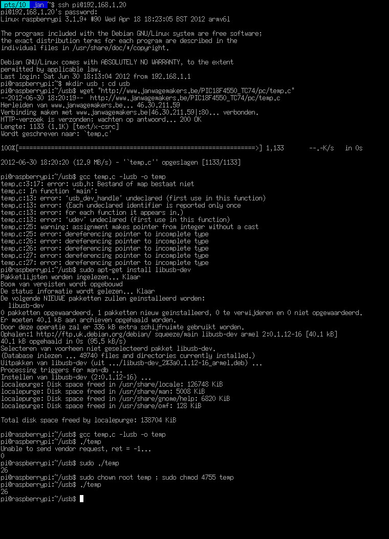
So, now that I have a Raspberry Pi and I can read the temperature with a TC74 over USB, I thought it would be nice to combine them together.
Because the Raspberry Pi makes use of the ARM architecture, a re-compilation of temp.c is necessary.
(click for larger image)
After compiling temp.c, everything just works like on a normal PC… Great! :)
As a test, I have then installed a webserver (boa) on the Raspberry Pi and created a little webpage that displays the current temperature.
The index.html of this simple webpage looks like this:
<html>
<head>
<meta http-equiv="Refresh" content="4">
</head>
<body style="margin:0px;" background="background.png" text="#000000"  bgcolor="#E0E0E0" link="#0000FF" vlink="#800080" alink="#FF0000">

<center>
<h1>Test : Raspberry Pi Debian GNU/Linux + PIC18F4550 TC74 USB</h1>
</center>
<hr>

<center>
<h2>The temperature is now <b><script type="text/javascript" src="/cgi-bin/temp"></script><noscript>No JavaScript support!</noscript></b>C.</h2>
</center>

</body>
</html>
And cgi-bin/temp looks like this:
#!/bin/bash
echo Content-type: text/html
echo
echo "document.write(\"`/home/pi/usb/temp`\");"
When I connect with a normal web browser to the Raspberry Pi, I get a simple webpage that displays the temperature:
It should also be possible to connect a TC74 directly (via I²C) to the GPIO pins of the Raspberry Pi, mmmm,… maybe something for a next post

Ways of Linking Raspberry Pi with Arduino Using GPIO, Serial, USB, I2C

Ways of Linking Raspberry Pi with Arduino Using GPIO, Serial, USB, I2C


There are only limited number of GPIO pins available on the Raspberry Pi, so it would be great to expand the input and output pins by linking Raspberry Pi with Arduino.
There are so many ways of connecting the Raspberry with Arduino. Recently [Oscar Liang] posted some tutorials on how to connect the two devices using different methods, including using USB cables, using GPIO pins on the Raspberry Pi and serial pins on the Arduino and using I2C communication.
arduino_plus_raspberry_pi_cropped-600x293

Linking Raspberry Pi with Arduino Using USB Cable

This is a very straight forward method, he basically setup serial communication on both devices, so they can be listened or write to each other. The Advantage about this is simplicity, all you need is a USB cable. The down side is, it takes up a valuable USB port, that you can use somewhere else.
raspberry-pi-to-arduino-via-usb-cable
Detail can be found here: http://blog.oscarliang.net/connect-raspberry-pi-and-arduino-usb-cable/

Linking Raspberry Pi with Arduino Using Serial Pins and GPIO Pins

Another Method is using the serial pins on the Arduino to connect to the GPIO pins on the Raspberry Pi.
This is in some way similar to the above connection, but this time we are not using the USB port. The bad news is, you might need extra hardware to run this safely –  a logic level converter because of the running voltage level difference between the two device.
There have been some arguments about whether a converter is needed on the internet. As some people suggest a voltage divider would do the job.  I won’t go through the technical detail here, but I strongly recommend using a logic level converter.
arduino-raspberry-pi-serial-gpio-connect-schematics
Detail can be found here: http://blog.oscarliang.net/raspberry-pi-and-arduino-connected-serial-gpio/

Linking Raspberry Pi with Arduino Using i2c Communication

This way is so far the best way we have seen on the internet – using I2C. It does not need any additional hardware (a couple of cables does not count), it does not use your USB port, and it’s very easy to setup as well.
Again there are concerns about the voltage level difference between the two devices (the Pi is on 3.3V and Arduino on 5V), if there were connected together the Pi might be damaged. However, it does not seem to be the case for I2C. It turns out there are pull-up resistors that protects the Pi.
Raspberry-PI-I2c-Arduino-connected
Detail can be found here: http://blog.oscarliang.net/raspberry-pi-arduino-connected-i2c/

Controlling LED brightness using PWM pic

Controlling LED brightness using PWM

A Guide to LED brightness control

Pulse Width Modulation or PWM is a term you hear a lot if you are interested in controlling power output using a microcontroller. It has many applications, although one of the most popular amongst hobbyists is controlling the brightness of LEDs. In this tutorial we will cover the basic principles behind PWM and how it can be used for LED brightness control including fading out LEDs rather than just turning them on and off.
This article will focus on some of the more specific details of the PIC18F range of microcontrollers; however the techniques and principles are the same for all other microcontroller products. Some microcontrollers include PWM modules which perform all of the hard work for you; however this article focuses on the more universal (and scalable) technique of using interrupts.


Contents

[hide]

Video Tutorial

This tutorial is primarily designed as a video tutorial. You can watch the full video on YouTube, please use 780p or 1080p for clearer diagrams:


Introduction

To control the brightness of an LED you can vary the power which is sent to the LED, for example using a potentiometer (variable resistor), the more power the LED receives the brighter it is, the less power it receives the dimmer it is. Microcontrollers are digital, meaning they only have two ‘power’ states, on and off. Although it is possible to supply a varying power from a microcontroller (using a Digital to Analogue Convertor (DAC)) this usually requires an additional chip. PWM provides the ability to ‘simulate’ varying levels of power by oscillating the output from the microcontroller.
If, over a short duration of time, we turn the LED on for 50% and off for 50%, the LED will appear half as bright since the total light output over the time duration is only half as much as 100% on. The important factor here is the ‘duration’, if we turn the light on and off too slowly the viewer will see the flashing of the LED not a constant light output which appears dimmer. The pulsing width (in this case 50%) is the important factor here. By varying (or ‘modulating’) the pulsing width we can effectively control the light output from the LED, hence the term PWM or Pulse Width Modulation.
50% Duty-Cycle
When using PWM it’s important to consider how slowly we can ‘flash’ the LED so that the viewer does not perceive the oscillation. The eye’s inability to see rapid oscillations of light is caused by our ‘persistence of vision’ which means, in very simple terms, we see the light as on even after it has turned off. This technique is how televisions display a seemingly moving picture which is actually made up of a number of different still frames displayed one after the other very rapidly. The minimum speed of an LED oscillating which can be seen by the human eye varies from person to person. However, for the purposes of this article, we will use a minimum speed of 50Hz, or 50 times per second (the same speed as used by European televisions).

Duty-Cycle

When using PWM there are certain terms which you will come across again and again. The most important term is ‘duty-cycle’. The duty-cycle refers to the total amount of time a pulse is ‘on’ over the duration of the cycle, so at 50% brightness the duty-cycle of the LED is 50%. The ‘cycle’ itself is measured (usually) in Hertz which gives us the cycles-per-second. So at 50Hz our cycle is 1 second divided by 50 cycles, which is 0.02 seconds. Since we are using such small time measurements it’s more useful to use microseconds (there are 1,000,000 microseconds in a second), this gives us a cycle duration of 20,000 microseconds which is 50 cycles per second or 50Hz.
During the 20,000 microseconds we have to turn the LED either on or off depending on the required duty-cycle so, for example, a 75% duty-cycle requires the pulse to be on for 15,000 microseconds and then off for 5,000 microseconds.
75% Duty-Cycle

PWM Resolution

The accuracy with which we can control the duty-cycle is known as the ‘PWM resolution’. The higher our PWM resolution is, the more levels of ‘brightness’ we can display. However, since the duty-cycle is ‘fixed’ at 50Hz more resolution requires finer timing from the microcontroller. The faster the microcontroller, the smaller durations it can time. Another limiting factor is the code execution, the microcontroller must not only time the ‘interrupt’ which causes the pulse generation, but also run the code which controls the LED output, which must complete before the next interrupt is called. In addition, you probably want your microcontroller to be performing tasks other than LED PWM brightness control, so there has to be some spare execution time between interrupts to do all of the other more general processing tasks.
With PWM control of LEDs the primary advantage of higher PWM resolutions is that it results in a smaller difference between ‘off’ and the lowest possible brightness from the LED. For example if our duty-cycle is 20,000 microseconds (50Hz) and our resolution is only 10,000 microseconds, the difference between ‘off’ and the lowest possible brightness will be 50% of the total possible brightness. At a resolution of 2,000 microseconds the difference would be 10% and so on. Overall the ‘PWM resolution’ dictates the number of brightness ‘levels’ we can support between completely off (0%) and completely on (100%). Again, the higher the resolution, the more timing accuracy and processing overhead is required.
10% PWM resolution
For your application the required resolution and overall duty-cycle may vary. Simple displays require very little precision control (and sometimes a little flickering is not the end of the world), for more advanced displays the ability to control levels of brightness might be critical (think of the issue of mixing colours using a RGB LED for example). The trade-off is simple, more control and accuracy requires more and more microcontroller resources. In this article we will focus on an example which supplies a resolution of 1,000 microseconds over a 20,000 microsecond duty-cycle (or 50Hz with steps of 5% giving us 20 levels of brightness). This level of control and accuracy is suitable for many purposes.

Timing the Interrupt

To perform the PWM using an interrupt we have to call the interrupt once every 1,000 microseconds and decide if the LED should be on or off. To do this we have to set up a timer on the microcontroller which calls the interrupt when it expires.
For this example we will take a Microchip PIC18F4550 microcontroller running at 48Mhz as the example. 48Mhz means the clock of the microcontroller will ‘tick’ 48,000,000 times a second. This is referred to as ‘Fosc’ (the Frequency of oscillation). A PIC18F4550 requires 4 ticks of the clock to process a single instruction. This means the smallest amount of time we can deal with using the microcontroller is a quarter of the clock rate, i.e. 48,000,000 / 4 = 12,000,000 (this is also known as Fosc/4), if there are 1,000,000 microseconds in a second, this means we execute a command around once every 0.0834 microseconds (12 MIPS (Million Instructions Per Second)). Although this is not quite correct in PWM terms since to generate a pulse we would need two commands (on and off) meaning a minimum cycle time of 0.167 microseconds (this effectively limits the highest frequency we can produce in software to 6Mhz, although this is not a very practical maximum).
If the Fosc/4 rate is 12,000,000 this means 1 microsecond of time passes for every 12 processor cycles. This means that 1,000 microseconds is equivalent to 12,000 processor cycles. This is important because with a 1:1 prescaler the PIC’s timers update once every processor cycle (although this is referred to as a 1:1 prescale, it really means no prescale at all). The timer’s prescaler slows down the rate at which the timer’s counter updates, with a 1:2 prescaler it updates once every 2 processor cycles, with a 1:4 prescaler it updates once every 4 processor cycles and so on.
To use an 8-bit timer (you can use a 16-bit timer also if you like) the maximum period the timer can measure is 256 ‘counts’ (0-255). Therefore we have to pick a prescaler value which allows us to time 12,000 processor cycles in less than 256 timer ticks. If we use a 1:64 prescaler we require 187.5 timer ticks to measure 1,000 microseconds:
12 processor cycles per microsecond, so 12 * 1000 = 12,000 processor cycles per 1,000 microseconds: 12,000 cycles / 64 (prescale) = 187.5 timer ‘ticks’
Since we cannot count a ‘half’ we simply round the figure down to the nearest integer (this means are resulting PWM will not be totally accurate, but for the purpose of controlling LED brightness this is not very critical). The higher prescale value we use, the less accurate the timing becomes. This can be corrected by using a 16-bit timer which allows us to count far more ticks and therefore use a lower prescale value.
For a PIC18F4550 this will result in code similar to the following excerpt where the timer0 module is configured, enabled and set to generate a low-priority interrupt:
 // Enable interrupts with priority
 IPEN = 1;
 
 // Set up timer0
 TMR0IP = 0;   // Set timer0 interrupt to low priority
 TMR0IF = 0;   // Clear the timer0 interrupt flag
 TMR0L = 255 - 187;  // Reset the timer0 counter
 
 T0CON = 0b11000101;  // Timer0 on, 8-bit and 1:64 prescaler
 TMR0IE = 1;   // Enable the timer0 interrupt
 
 // Enable interrupts
 GIEH = 1;   // Global enable all high priority interrupts
 GIEL = 1;   // Global enable all low priority interrupts
Once the timer is configured and running we need some interrupt code to decide if the LED should be on or off for the interrupt. Since we have 20 possible brightness levels (and therefore 20 steps of resolution in our PWM generation) we can simply use a counter which counts from 0-19 and is updated once every interrupt. If the brightness of the LED is represented using a number from 0-19 we simply have to check if the PWM counter is higher or lower than the brightness number to see if the LED should be on or off.
// Globals for PWM
unsigned char pwmCounter = 0;
unsigned char ledBrightness = 0;
 
// Low priority interrupt procedure
void interrupt low_priority lpHandler(void)
{
 // Is this timer0 interrupting?
 if (TMR0IF)
 {
  if (ledBrightness > pwmCounter)
   LED0 = 1; else LED0 = 0;
 
  pwmCounter++;
  if (pwmCounter > 19)
   pwmCounter = 0;
 
  // Get ready for the next interrupt
  TMR0L = 255 - 187; // Reset the timer0 counter
  TMR0IF = 0;  // Clear the timer0 interrupt flag
 }
}

Fading the LED

Since we know the cycle duration of the timer0 timer we can also use this to provide fading effects on the LED. To do this we have to store two values for the LED brightness, one variable to store the actual displayed brightness and another to store the target brightness for the LED. Since we only want fade off (you could adapt this easily to support both fade on and fade off) if the target brightness is higher than the actual brightness, we immediately bring the actual brightness to the same level.
However, for fading off we want to decrement the actual brightness level one step at a time until it equals the target brightness. Since there are only 20 levels of brightness we cannot simply subtract a level on each interrupt call since the interrupt call is too fast for the fade to be perceived by the viewer (20 calls would only consume 20,000 microseconds which is too fast to see).
Instead we keep another counter which counts a number of interrupt calls which should occur in between decrementing the actual fade level. Since we know the interrupt is called every 1,000 microseconds it’s pretty straight-forward to work out how many interrupts we should count to get a desired fading rate. For example, if we want a fade from brightness level 19 to 0 to take 0.5 seconds we simply divide the required time (in microseconds) by the interrupt time of 1,000 microseconds and then by the number of levels. Therefore 0.5 seconds (or 500,000 microseconds) = 500,000 / 1,000 = 500 /20 = 25. This is shown in the following code excerpt:
// Globals for PWM
unsigned char pwmCounter = 0;
unsigned char ledActualBrightness = 0;
unsigned char ledTargetBrightness = 0;
 
unsigned char fadeCounter = 0;
 
// Low priority interrupt procedure
void interrupt low_priority lpHandler(void)
{
 // Is this timer0 interrupting?
 if (TMR0IF)
 {
  // Perform the PWM brightness control
  if (ledActualBrightness > pwmCounter)
   LED0 = 1; else LED0 = 0;
 
  pwmCounter++;
  if (pwmCounter > 19) pwmCounter = 0;
 
  // Perform fading control
  if (ledTargetBrightness >= ledActualBrightness)
   ledActualBrightness = ledTargetBrightness;
  else
  {
   fadeCounter++;
   if (fadeCounter == 24)
   {
    ledActualBrightness--;
    fadeCounter = 0;
   } 
  } 
 
  // Get ready for the next interrupt
  TMR0L = 255 - 187; // Reset the timer0 counter
  TMR0IF = 0;  // Clear the timer0 interrupt flag
 }
}

Conclusions

Whilst it is perfectly possible to get PWM controls to work with LEDs using pure guess work, calculating the desired optimum values makes more efficient use of the available processor resources allowing you to both do more with the microcontroller and/or control more LEDs simultaneously from the same chip. The same techniques shown here for LEDs can also be used to control motors, analogue meter displays, incandescent light bulbs, etc.

Popular Posts


© 2013 Antikythera Electronica y domotica. All rights resevered. Designed by Templateism

Back To Top